Model SG81
Introduction
This coil was originally built Fall/Winter of 2011 after outgrowing the 4” secondary that I had built nearly 10 years prior. It was originally designed to handle between 3kW-10kW of input power, with 10kW being the absolute upper maximum. It would be powered initially by a single 12kV PT, with the intent of eventually stepping up to pole transformer power as other components were acquired. The decade of experience running Tesla coils had taught me a few things about do’s/do not’s, and some features that I wanted in a new coil. Particularly: portability, modularity, flexibility, adequate primary-secondary spacing, more robust RF ground and topload connections, and better overall aesthetics.
Specs as of 2018/10/06
- Secondary: 8.25” x 34” winding length, 24AWG wire
- 83.37 kHz resonant frequency
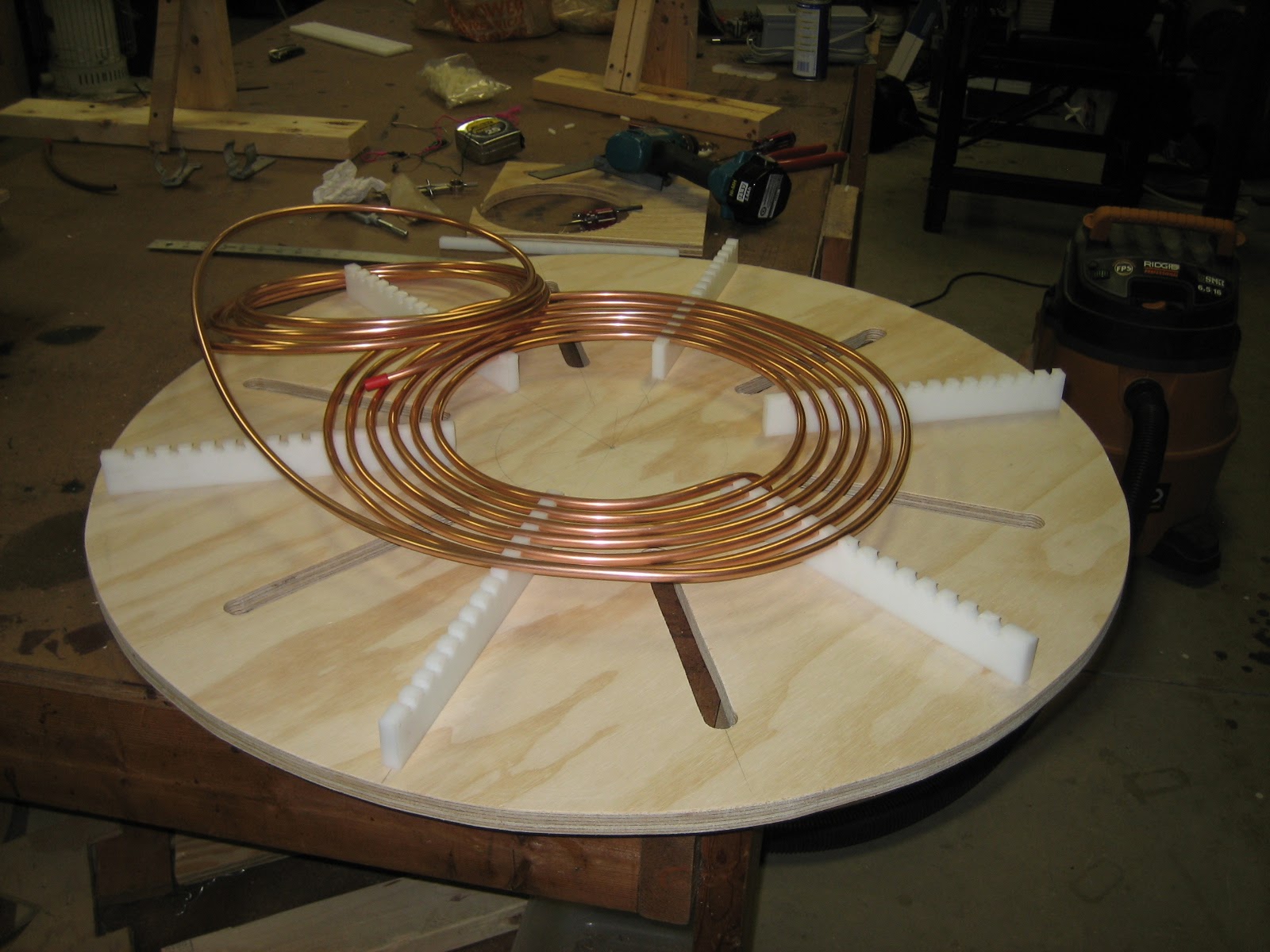
- Primary: 15T of 3/8” soft copper tubing, 3/8” edge-edge spacing
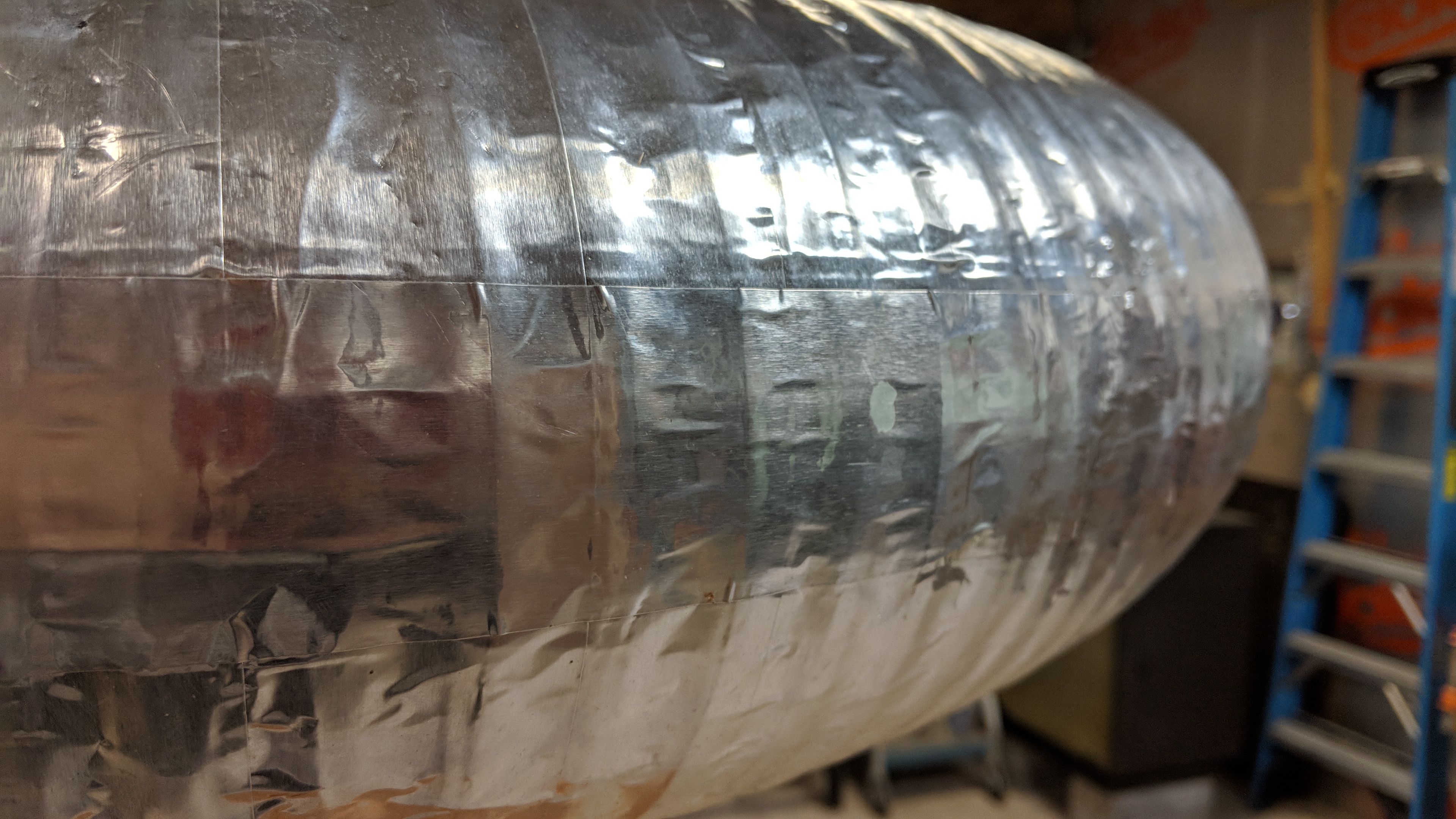
- Topload: 34” x 8” corrugated drain pipe covered with foil tape
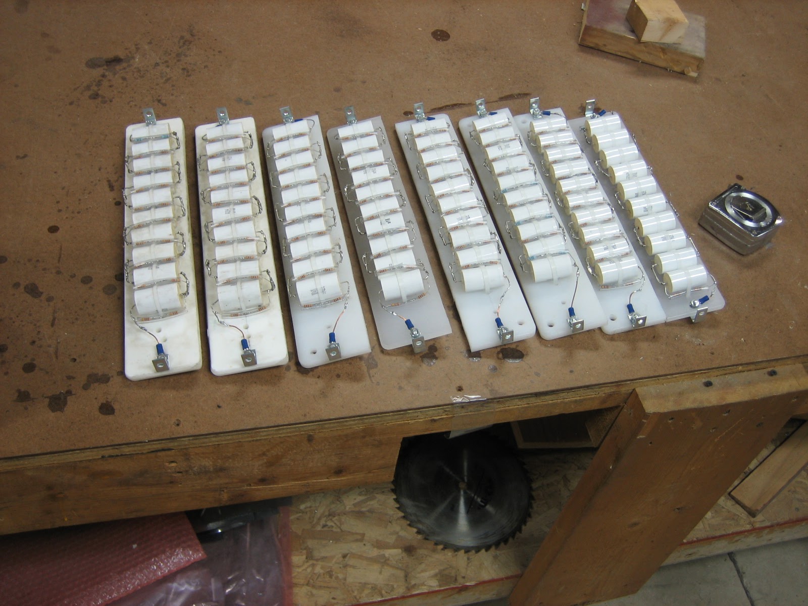
- Capacitor: 4x20 CDE942C20P15K MMC, 0.03uF @40KVDC
- Power Supply: 2x GE JVM-5 100:1 (12kVAC, 1500VA nominal power) PTs in series/parallel
- ~30A, 240V input
- Secondaries in series, primaries in parallel
- Ballasted with a Miller Thunderbolt welder
- Gap: 12” ARSG, 8 flying, 2 stationary electrodes (all 1/4” pure tungsten)
Design
The secondary, topload, primary assembly, and base can all be broken down separately to ease transporation and storage. The base is large enough to enclose the newly built 12” ARSG and MMC capacitors. The secondary has absolutely no metal penetrating the coil form or end caps. The end caps are HDPE discs held in place with nylon bolts. Topload connection is done via 3” SCH40 PVC flanges and various lengths of pipe to set the topload heigh, or allow for topload stacking.
Secondary
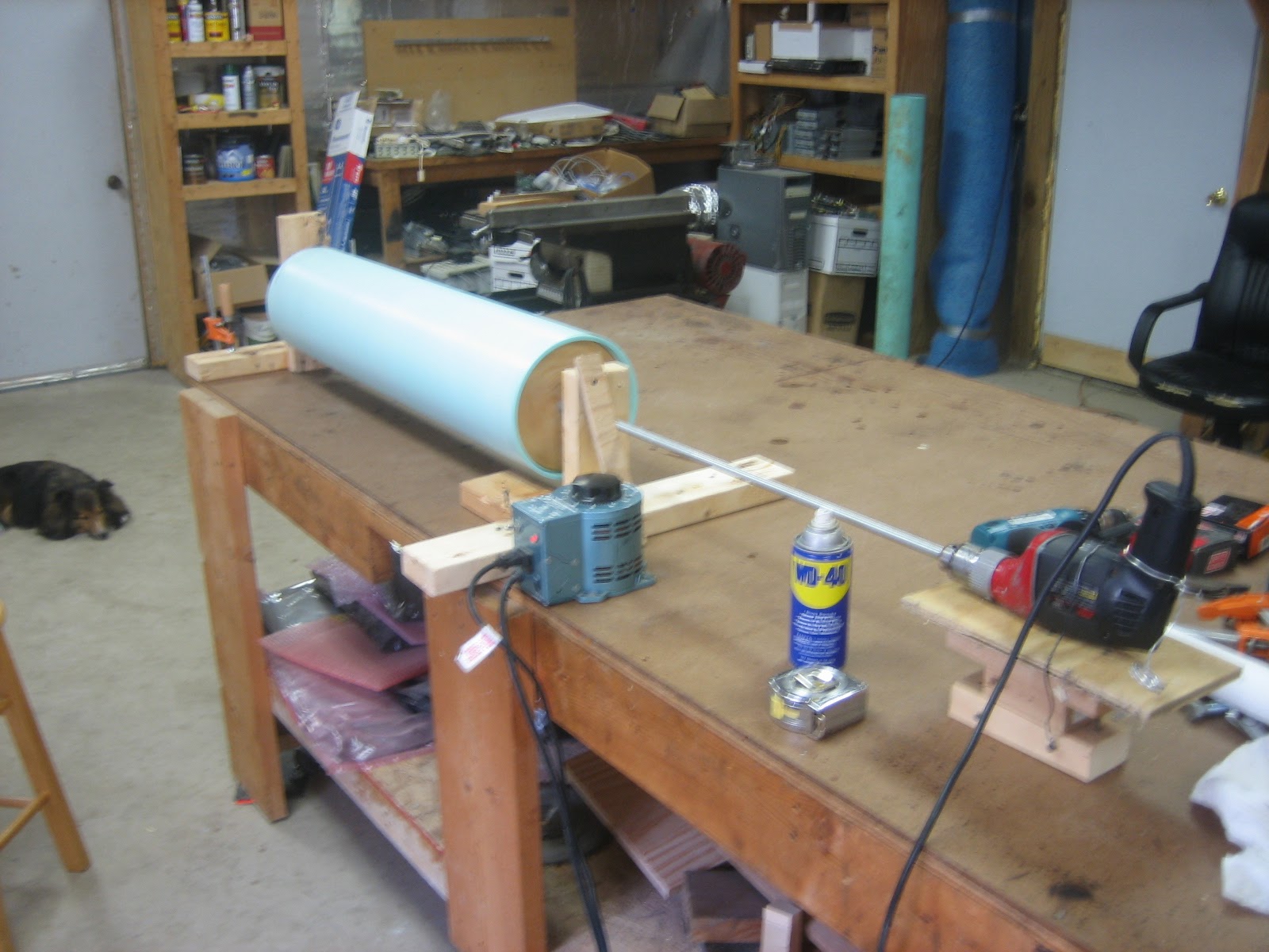
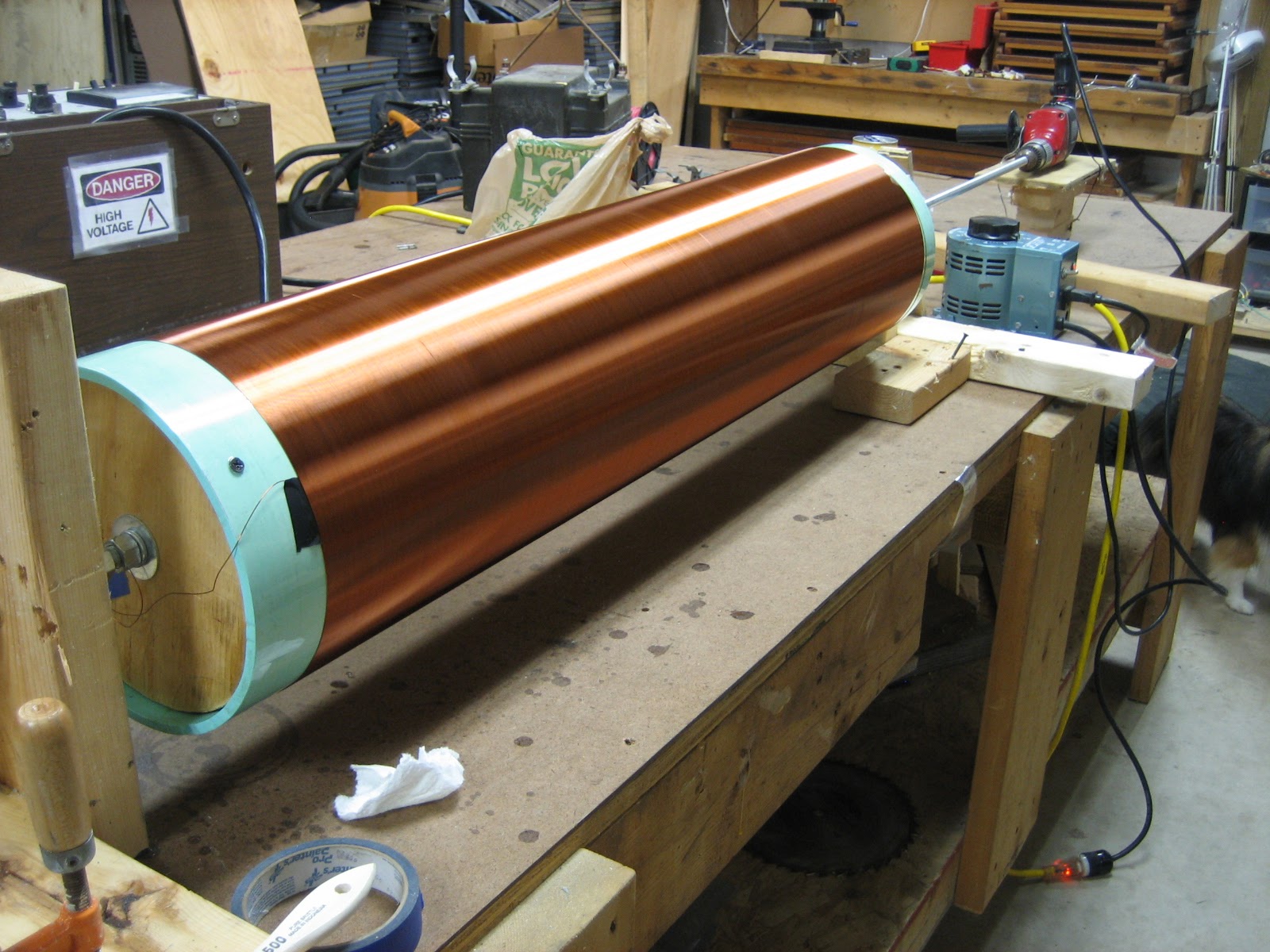
The secondary coil form was sanded, coated with polyurethane, then wound by hand with the assistance of a corded drill run off a variac to reduce the speed. After winding, it was coated with may layers of polyurethane, then allowed to slowly rotate while curing.
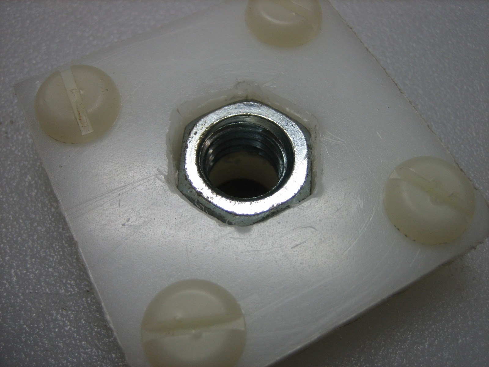
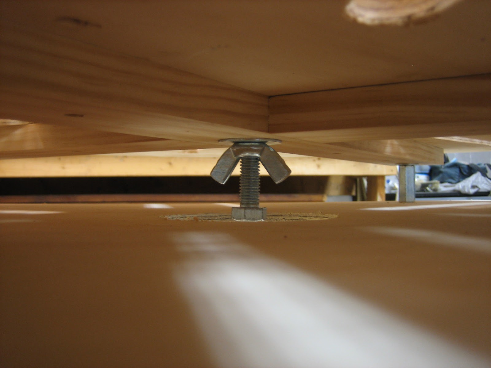
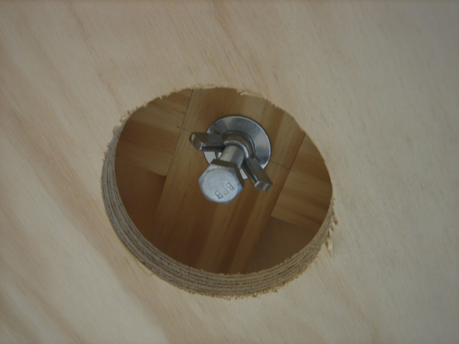
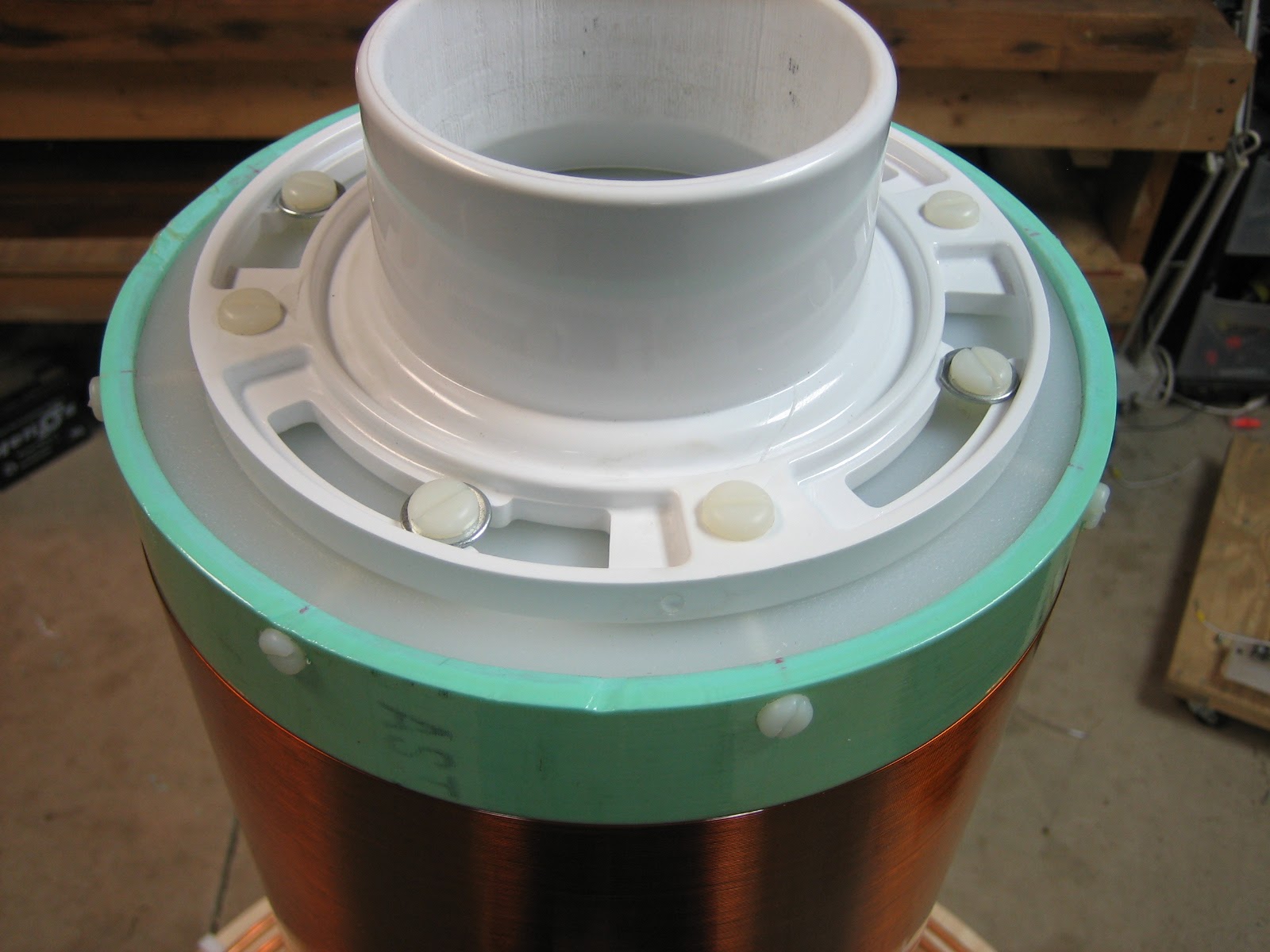
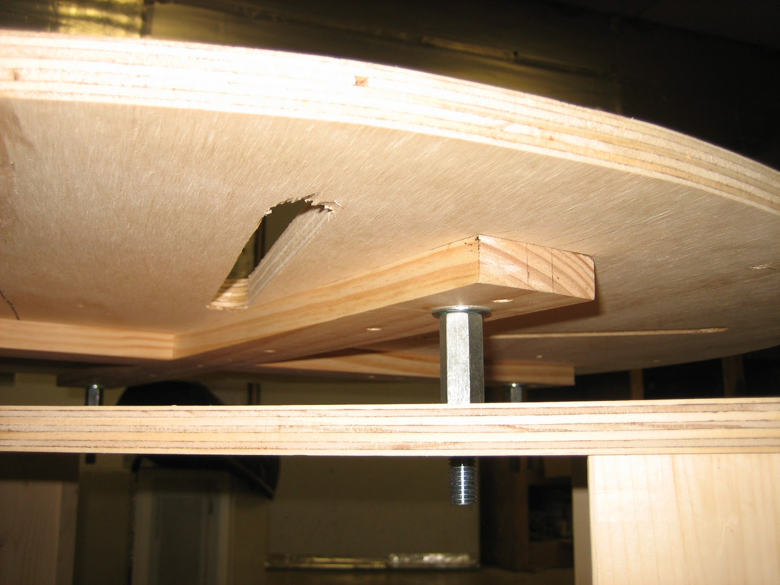
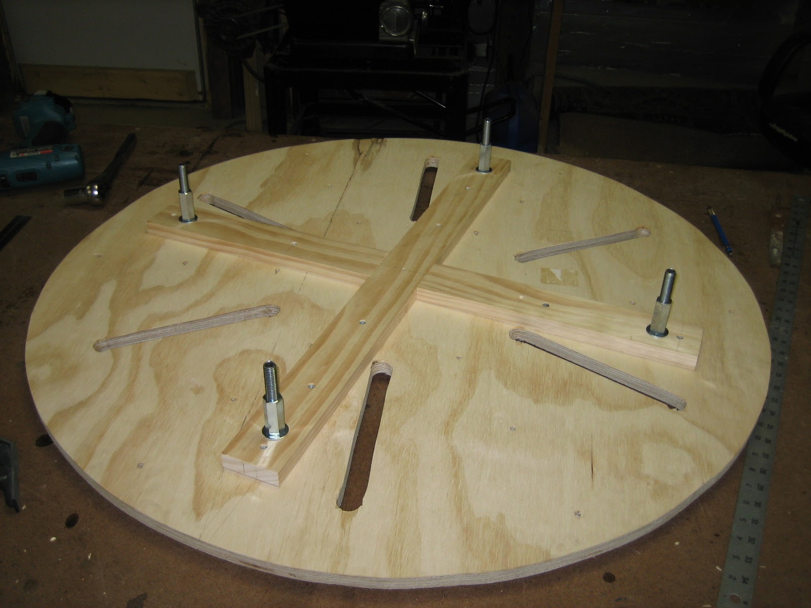
To mount the secondary, a 1/2”-13 hex nut is captured in a block of HDPE (epoxied together), then bolted to the end cap with nylon screws. A 1/2”-13 bolt with wingnut and washer can then be used from the bottom of the primary deck to securely hold the secondary in place, while allowing the secondary to be quickly removed for storage and transportation. The bolt and nut are not electrically connected to anything, and are effectively insulated from inside the coil form.


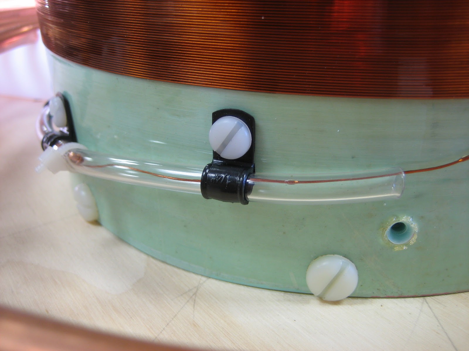
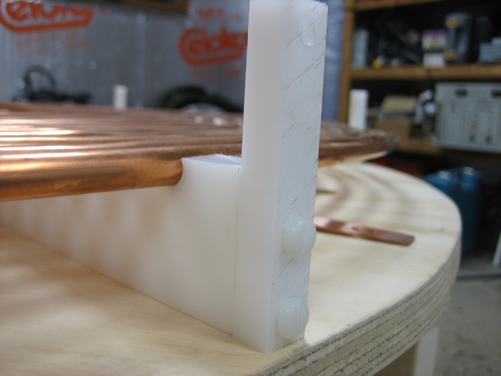
The top of the secondary is capped with a piece of HDPE and nylon screws, then topped with a 3” PVC pipe flange with more nylon screws.
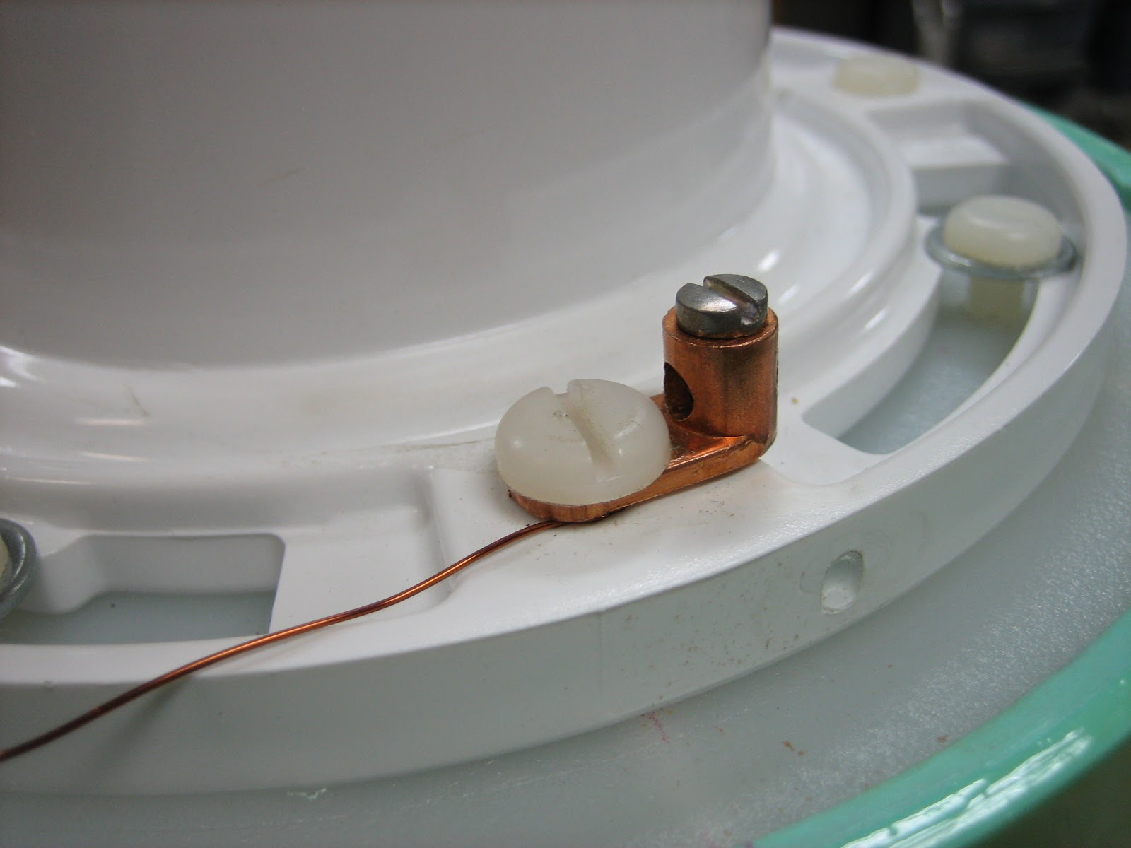
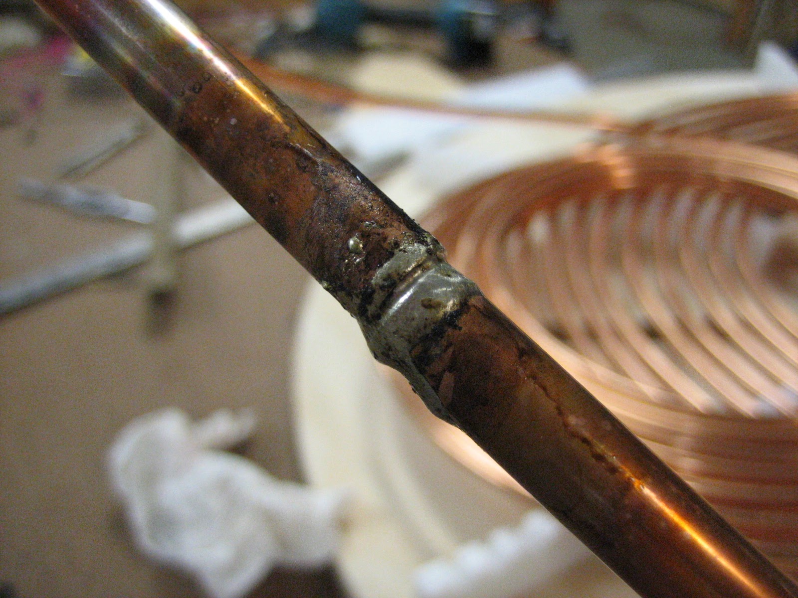
Detailed pictures of the top and bottom secondary electrical connections, which allows for stress-free connections.

Primary


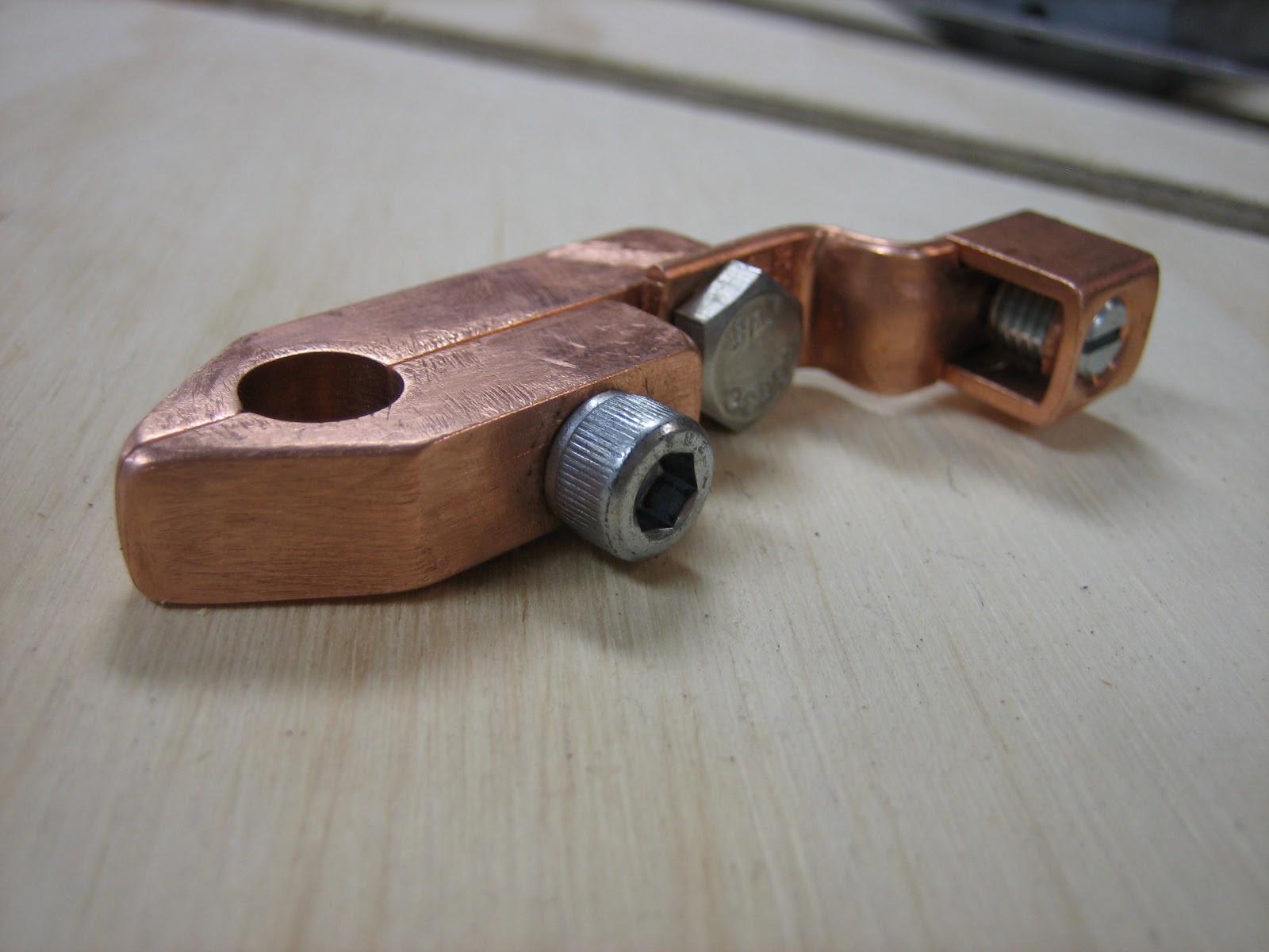
Simple primary tap made from pure copper bar stock and some hardware.
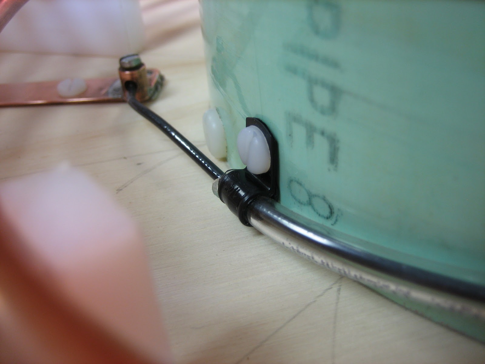
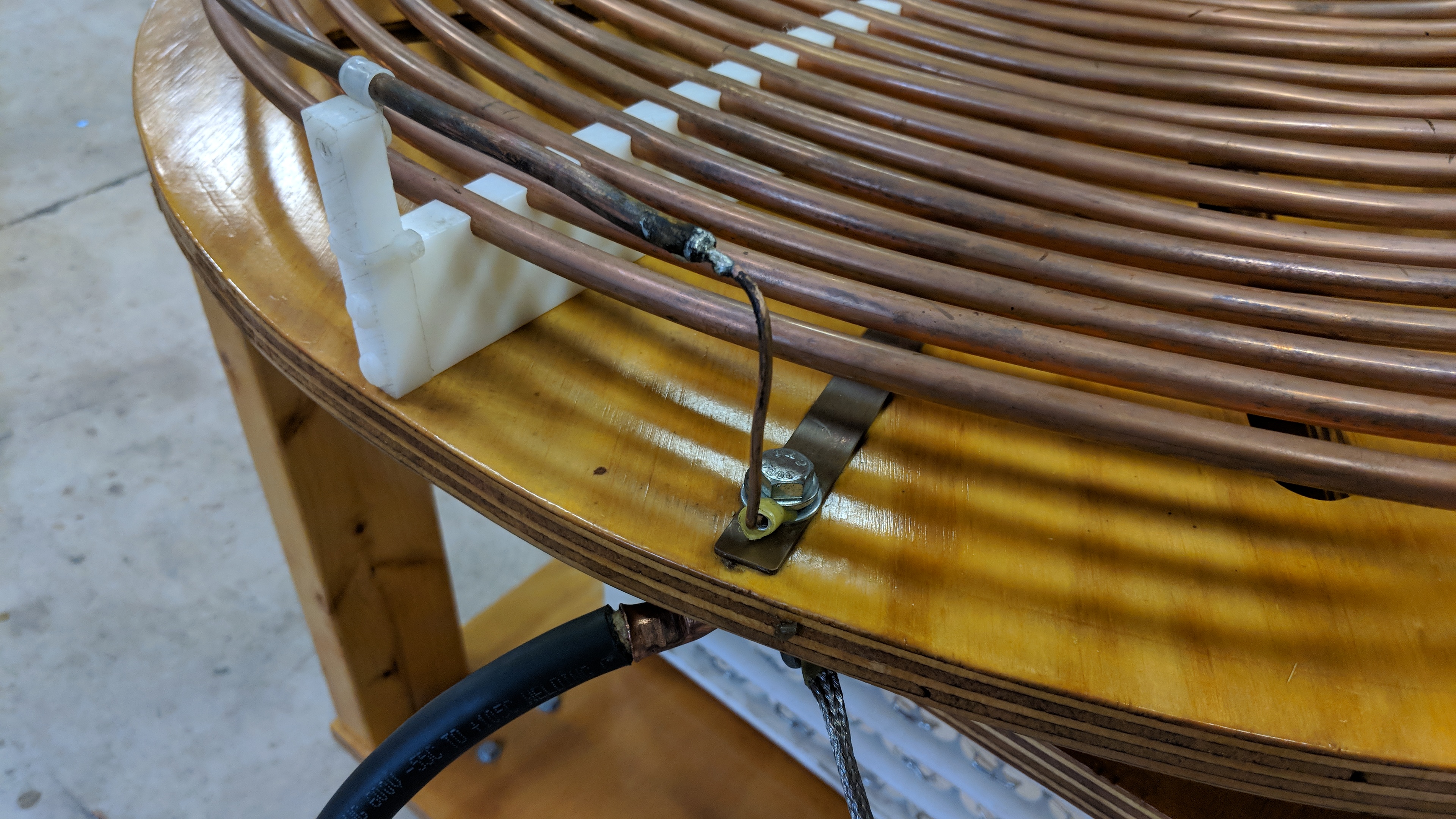
Detail showing the connection between the main RF ground (2 / 0 welding cable), ground braid going to the safety gap, and the connection to the strike rail.
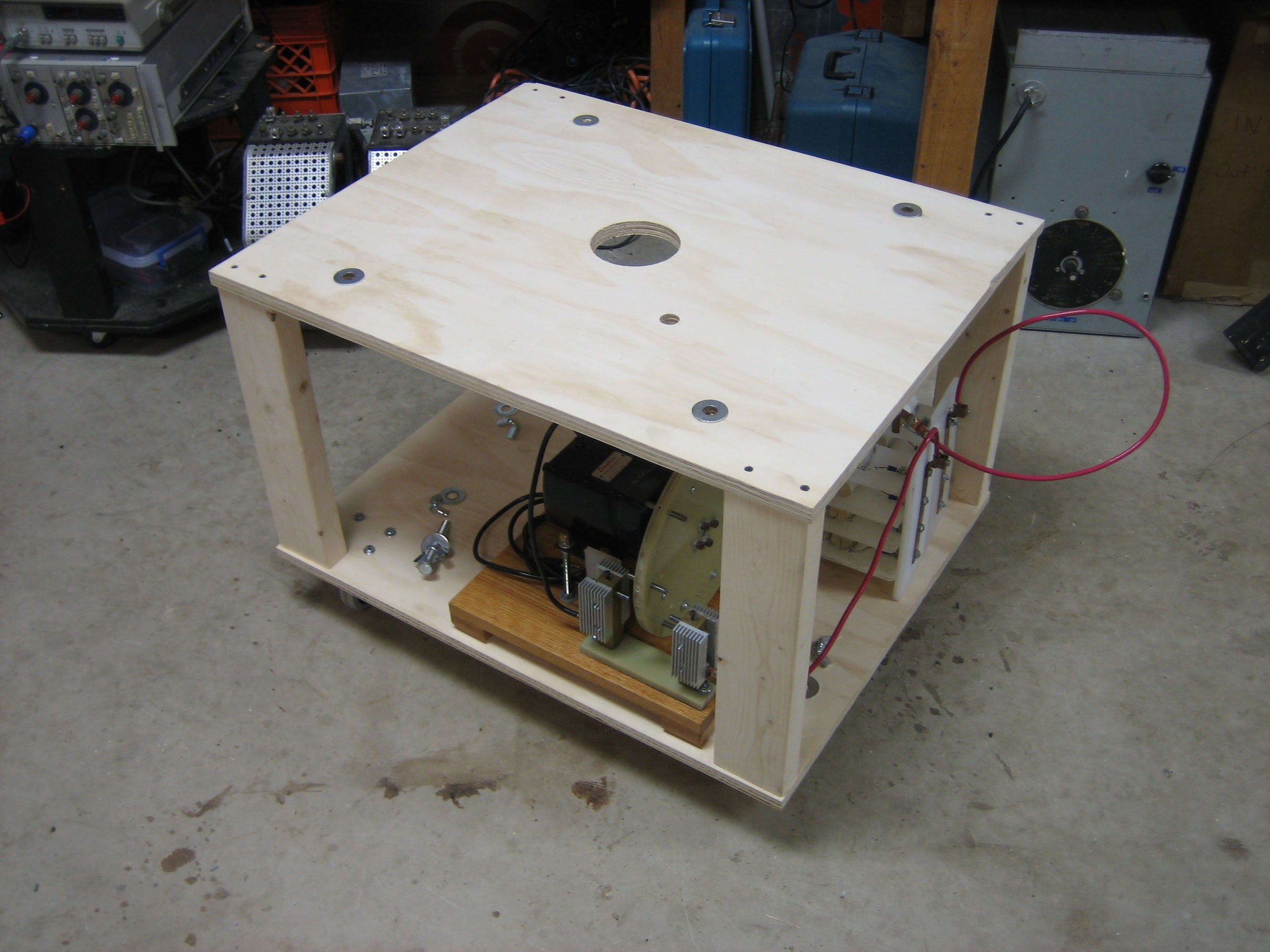
Base
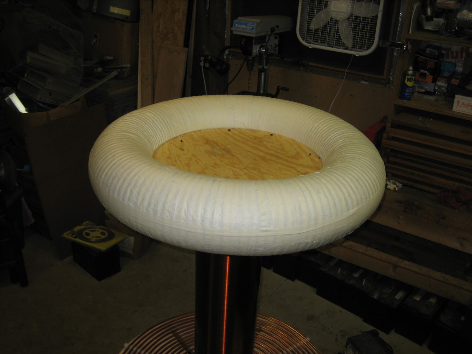
Toroid
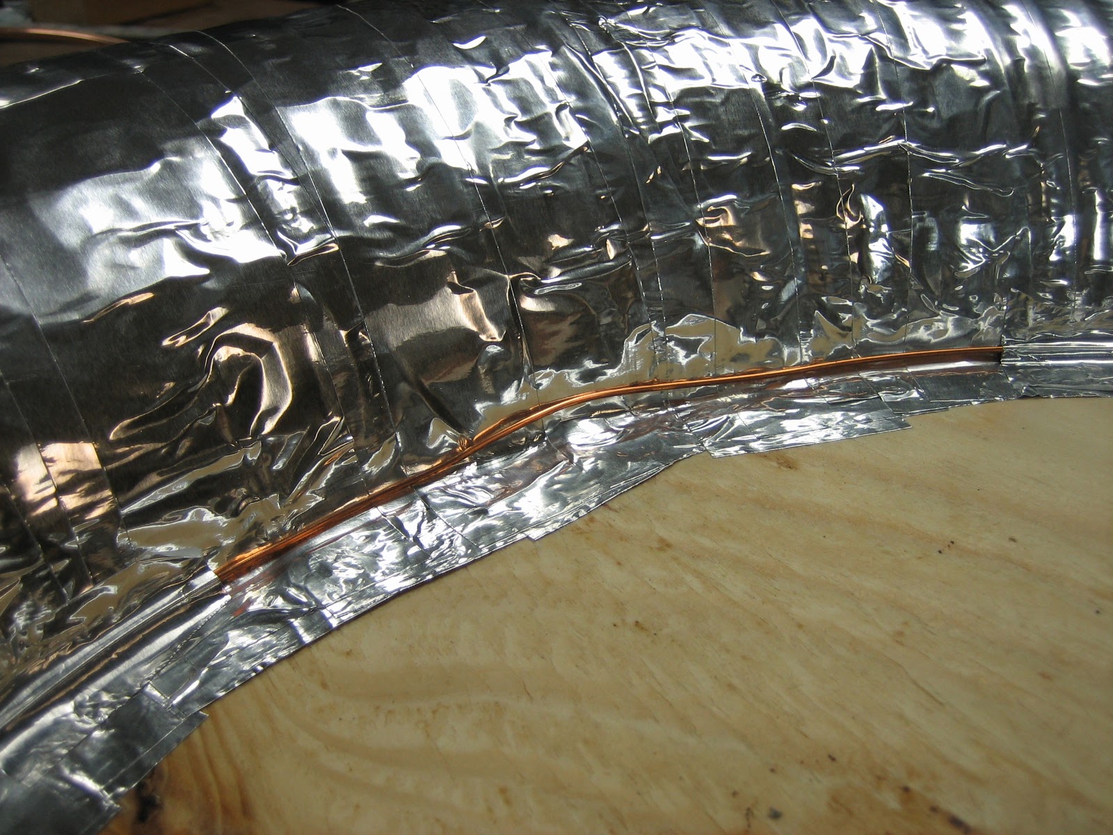
The toroid is a piece of 8” corrugated ABS drain pipe, covered with may layers of wide masking tape the smooth it out, then mounted over a plywood center disc. A piece of copper wire is embedded in the inside upper edge to provide solid electrical connection to each piece of foil tape (arcing between adjacent pieces of tape was noted in other toroids, this wire totally eliminates this problem). Finally, a single piece of tape is placed around the outer edge to help smooth the outer diameter and reduce sharp edges caused by the pieces of tape underneath.


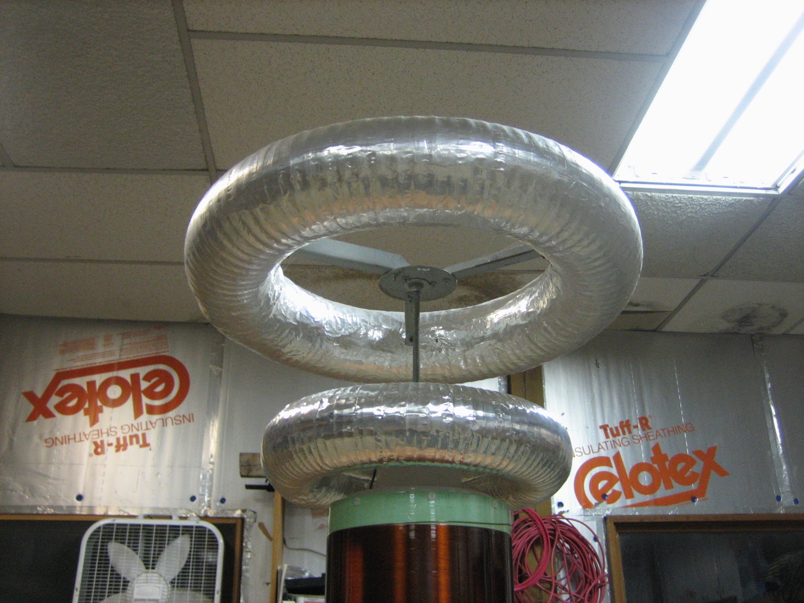
Showing an alternate topload configuration using two smaller toploads. Performance was better with the single large topload, despite requiring off-axis inductance to bring the system in tune.
MMC
A thermal image showing MMC cap temperatures. Note that the ends of the CDE 942C series capacitors is very reflective, so the few caps that are showing high temperatures may just be reflecting the body heat of the cameraman.
Off-axis L
As a result of the high inductance, low frequency secondary, an off-axis coil is required in series with the primary to bring the system in tune with the 0.03uF capacitor. This was originally 12AWG THHN wound on a 3” PVC form, but this got quite hot even during short runs. In September 2018, this was replaced with a hand-wound coil of 8AWG wire, which still got quite hot but only during 1min+ runs.
The thermal image shows the coil of wire after almost a minute of continuous high power operation.
Performance
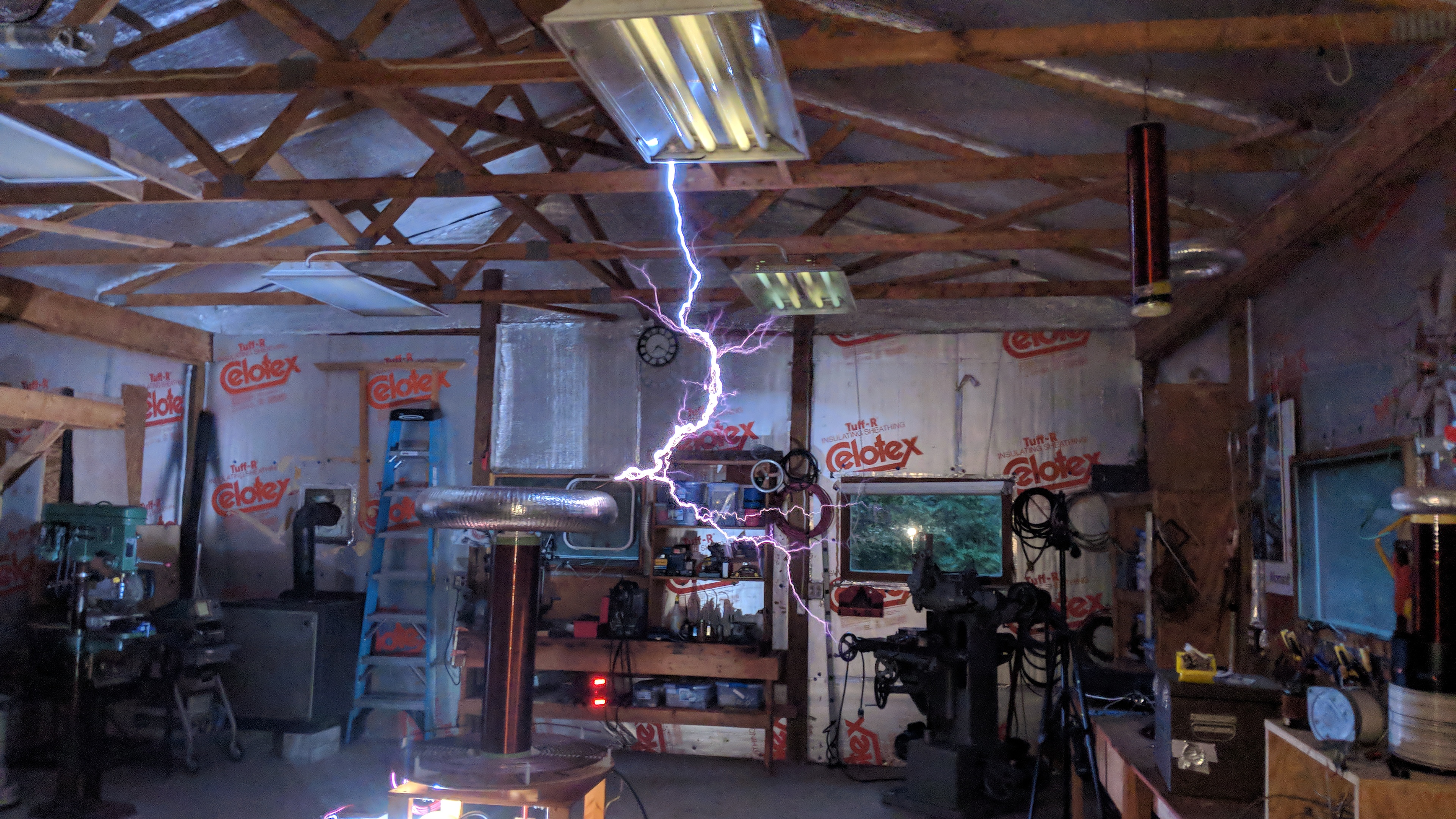
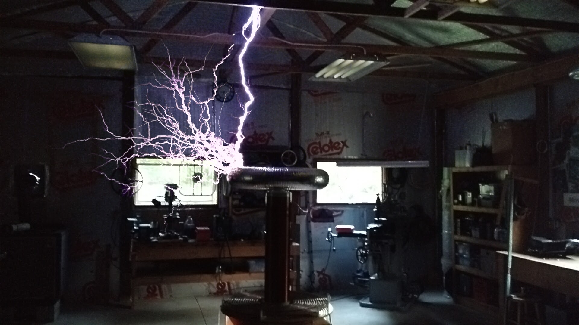
The coil continuously throws 6 foot power arcs to ground, currently limited by proximity of the fluorescent lights and rafters. This is with lightly pegging the 25A ammeter in the power controller, with ~280V in (stepped up via a 1256D variac). An outdoor run will be conducted soon once a NEMA 6-50P to L6-30R power adapter is assembled and the weather cooperates.
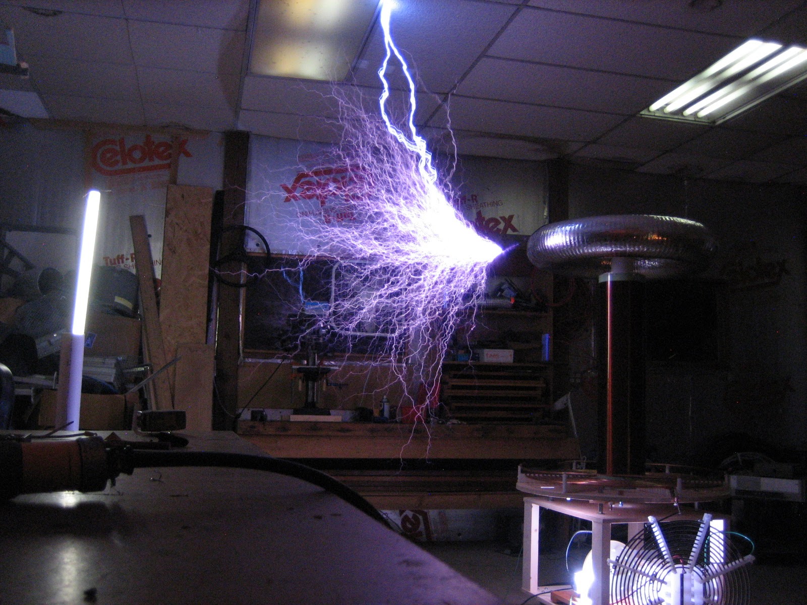
Some of the first runs at ~3kW from a single 12kV PT.
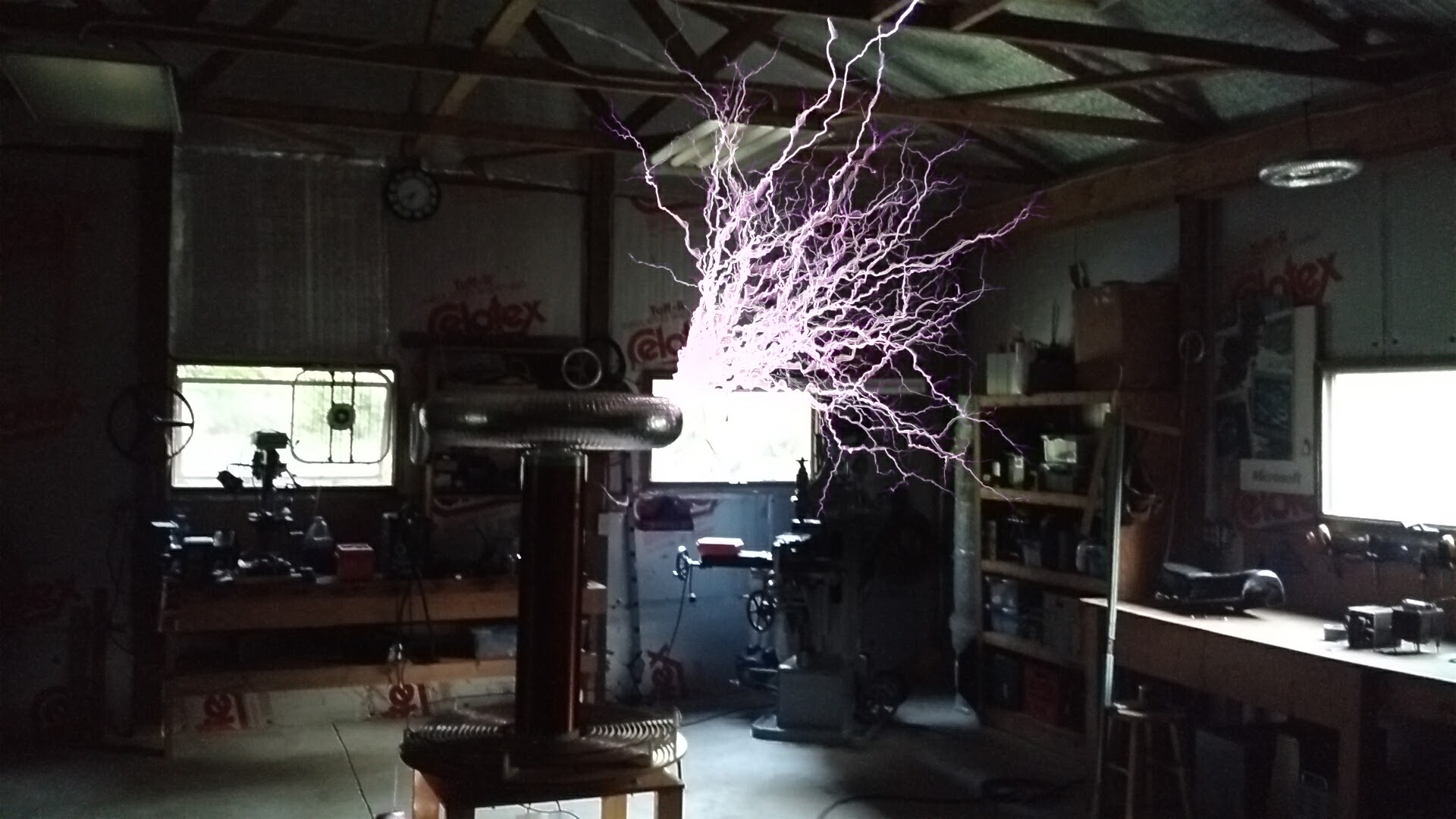
Later run after doubling the power, and various other improvements.
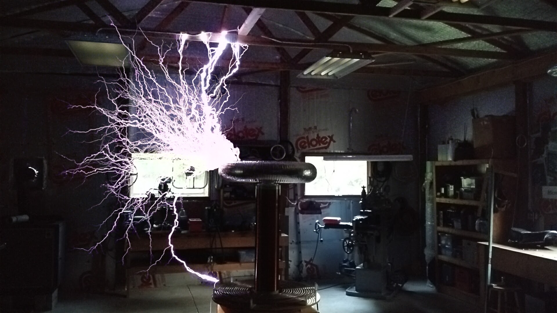
Composite image from my Pixel2 in burst mode.