Model DR81 #
Specs#
- Secondary: 8.25” x 34” winding length, 24AWG wire (same as 81G)
- Topload: 34” x 8” corrugated drain pipe covered with foil tape (same as 81G)
- Primary: 15T of 3/8” soft copper tubing, 3/8” edge-edge spacing (same as 81G)
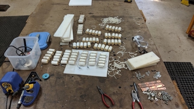
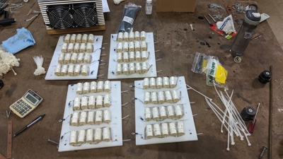
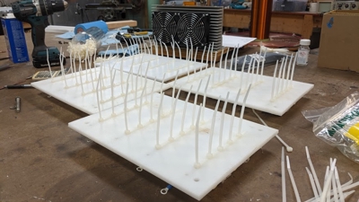
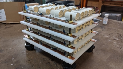
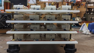
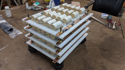
- Primary Capacitor: 5s16p CDE942C20P15K MMC, 0.48uF @10KVDC, 216A RMS, 6912A peak
- Frequency: Secondary system is 70kHz, primary is detuned to roughly 65kHz (turn 4)
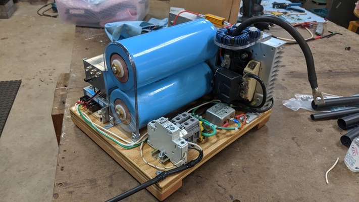
- Bridge
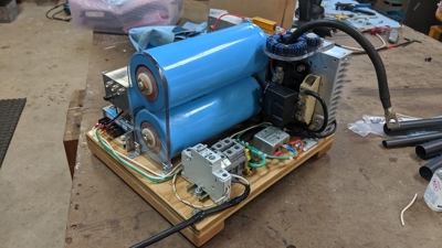
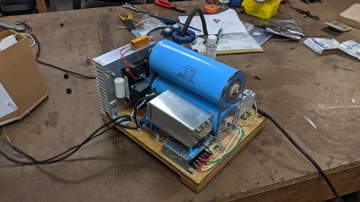
- Layout: H-bridge with voltage doubler for 680VDC with 240VAC input
- IGBT: 2x Mitsubishi CM300DY-24H
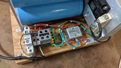
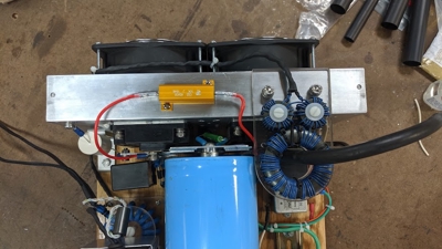
- Bus capacitor: 5500uF @ 900VDC. 2x CDE 520C 11000uF, 450VDC inverter-grade electrolytic in series. 15kOhm / 10W bleeder/balance resistors
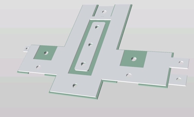
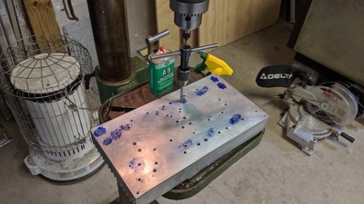
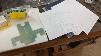
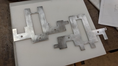
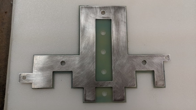
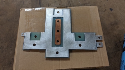
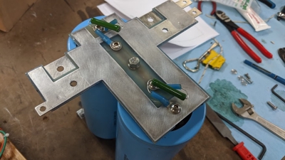
- Bus: Laminated, 1/16” aluminum, 1/16” G10/FR4 insulating layer
- Rectifier: Semikron semipak SKKD81/16
- Snubber: 2x Aerovox RBPS direct-mount, 2uF 1000VDC each
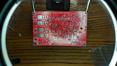
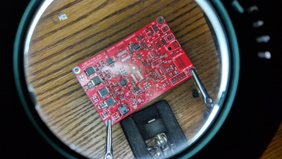
- Driver: UD2.7C
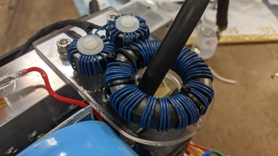
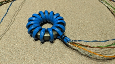
- Feedback/OCD: 50:20:1 current transformers, Fair-rite Type 77 (5977003801 and 5977006401)
- Interrupter: Dual Channel MIDI Interrupter
- OCD: Currently set to 800A. Could probably handle 1000A+
- Arc length: ~7ft with ~200VAC input running ~45uS on-time while playing music.
Introduction#
In early 2018, I was bit by the DRSSTC bug when it became apparent just how much heavy iron I had accumulated in my quest to bring my 15kVA Pole Pig powered SGTC online.
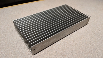
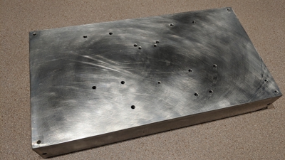
I already had a large heatsink salvaged from a 7kVA UPS system. I figured I could reconfigure my existing CDE 942C MMC to get one good for 0.48uF, 10kVDC 216A RMS. I simply needed a driver, bus caps, interrupter, IGBTs, laminated bus, gate drive transformer, and a few other odds and ends to construct the bridge.
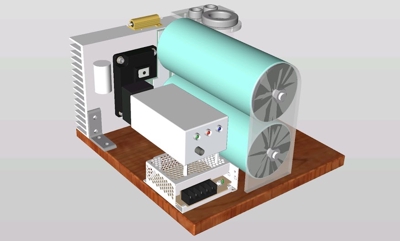
This coil is based around a full bridge of CM300DY-24H modules, a voltage doubler arrangement for 5500uF @900VDC, Gao Guangyan’s UD 2.7 driver, and the same 8” secondary and 3/8” primary from the 8” SGTC”.
This coil saw first-light Sept 17 2019, and the first full-power run was conducted Sept 21 2019 without any issues whatsoever.
Construction#
Bridge#
MMC#
Driver#
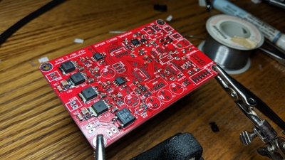
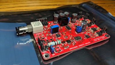
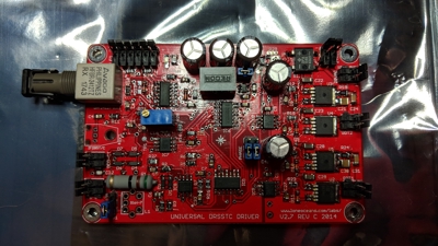
The driver is Loneocean’s UD 2.7C, with the HFBR series ST fiber module installed.
Testing#
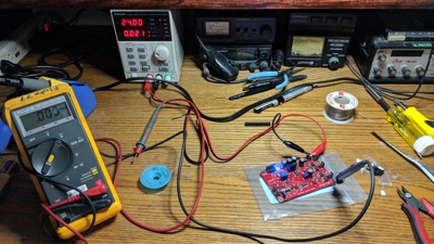
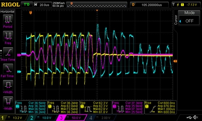
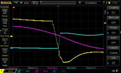
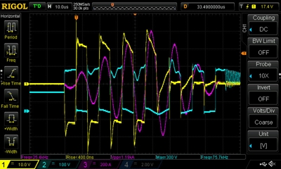
Results of low-power testing were promising. Phase lead was adjusted for minimal ringing on the DC bus.
- Yellow: Gate voltage
- Cyan: Bus voltage
- Magenta: Primary current
